|
This page focuses on ways to make an I-36 go safe and fast to your desired port of call. We share the ways people have set up their navigation stations and electronics, and various layouts for running gear from boom vangs and travelers to all of the control lines, sheets and go-fasts. We'll even try to get some racers to contribute their sail trim secrets. Pictures and dialog are the rule. If you are looking for major, essential item care and maintenance, (including standing rigging) look on the Maintenance page. Other stuff to make life aboard for fun or at least easier, can be found on the Gadgets page. We will continue to add information as it is received, so please send your contributions to: E-mail Rick Van Mell. |
Gary,
Attached please find pictures of the instrument arch assembly I mounted
over the companion way of my 1974 Islander 36, Frolic. The Raytheon ST60
depth and speed instruments are mounted in a four-instrument Navpod. The
Navpod is mounted on a custom stainless steel (one inch diameter tube) arch.
(If there is enough interest I can make an electronic sketch of the arch
and send it to you.)
The new instruments replace a variety of Signets that were mounted on
the cockpit "backrests" and sometimes worked. Three were mounted on on
port, two on starboard. I fiberglassed (polyester) the holes over and just
finished painting (one-part polyurethane) the new surfaces. (I have
not yet fixed the headliner where I needed to access the base of the arch....)
Our ST4000+ autopilot panel (added after the pictures below were taken) is mounted next to the speed and depth displays shown.
I mounted the fluxgate compass on the port bulkhead, next to the companionway, about 2 ft above the engine. Seems to work fine.
I had already interfaced my Garmin 45XL to the Raytheon SL70 radar so lat/lon was displayed on the radar, along with the ST60 speed and depth. I expected that the seatalk cable connecting the radar to the instruments in the pod would give GPS data to the autopilot, but this did not work! I had to run an additional twisted pair of wires from the GPS output to the autopilot display head to make it work.
I am very happy with the improved ergonomics of the arrangement. I
have no problem seeing the instruments from the wheel, even with sleeping
passengers! I plan to add wind instruments at some point. If I did
this again, I'd consider using 1-1/4 inch tube for the arch to make wiring
easier. The arch bends might be too tight for 1-1/4 tubing, however....
(The radar is mounted on a swing arm so I can see it inside or from the
cockpit.)
Fair winds,
Steve Hodges
hodgmojo@home.com
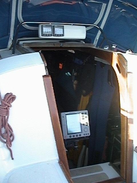 The new pod.
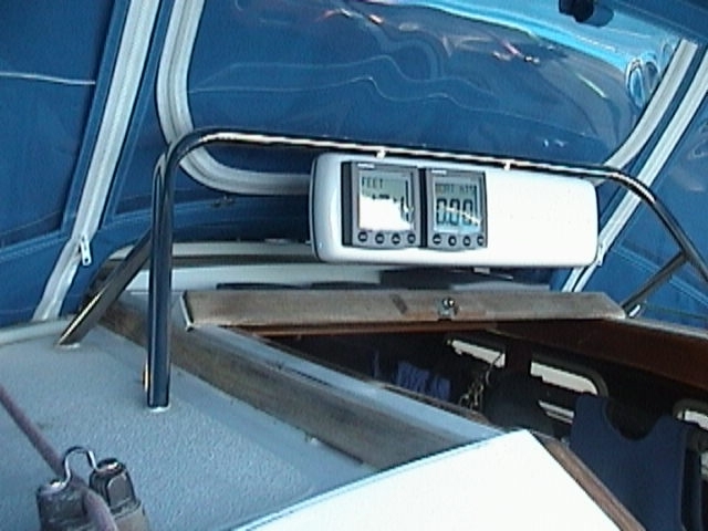 The instruments up close.
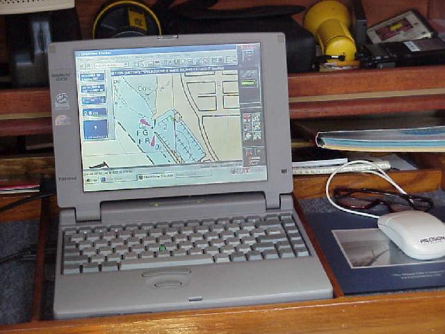
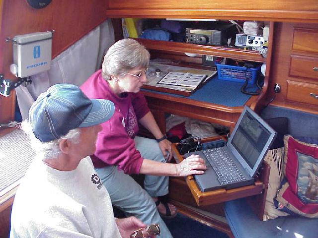
Don Henderson on Kindred Spirits fixed up this handy rig to hold a Garmin 45 GPS, and computer and paperwork. He is using Chart View. The GPS will pick up signals down below, though more slowly than when on deck. Its cord is long enough that it can be set on a cockpit seat to get faster response. Note the little blocks that hold the tray in place just above the "V" on the Chart View handbook.)
Above the nav station you can see their VHF and extra speaker which is on a long lead and can be easily moved to the cockpit. And finally, the stereo for tunes with one speaker whose pair is mounted forward on the head bulkhead.
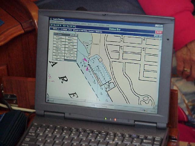
The second picture shows the level of detail available for Vallejo YC harbor, and you can just make out the small green boat shape located on the north end of the dock at the clubhouse - just where she was tied up for the picture.
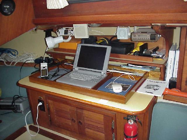
Nancy & Al Farnum are shoving off on Silver Shadow in July 1999 for a two month cruise down the coast of California to San Diego and back. They have done wondrous things to their boat for navigation and life at sea. The first picture shows Nancy at their computer table which swings out from the navigation locker. The table clicks in to a clip on the inside of the nav locker door for support. This angle is designed so the unit can be read from the cockpit bench. The computer is wired to the GPS which is mounted at the helm. The wiring includes both power and the computer connection so there is only one connection to be made when the GPS is installed. They use Cap'n software.
The computer table also has a support which drops down from the bottom and can be firmly connected to the frame of the nav locker to provide a very sturdy desk-like surface for extended work. A fold down seat has been built on the port side of the companionway steps to complete the installation. (Nancy is sitting on it!) Above the nav table there is the ham/SSB radio, and the VHF.
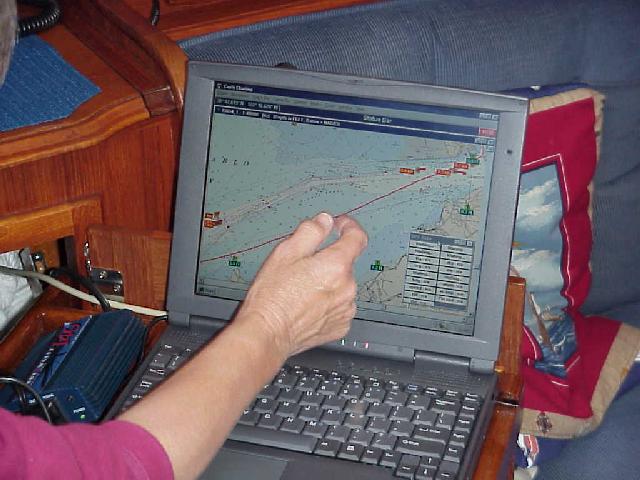
The second pic shows their view of Vallejo harbor, but the GPS is not turned on. The third pic shows how the system tracked their course up San Pablo Bay between Pt. Pinole and the entrance to the Napa River. The software even inserted the little red current direction and strength arrows.
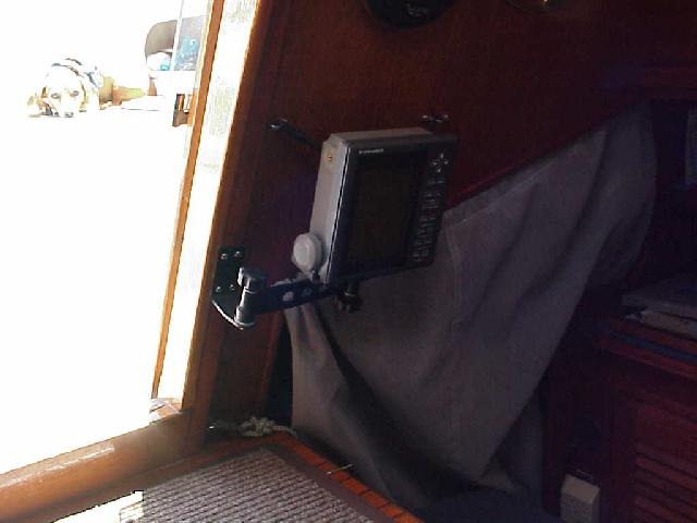
Oh yes, the radar unit is neatly mounted on a swing bracket so it can be read in the nav station or in the cockpit, as shown in pic four. The radar unit is neatly mounted on a stainless tube which runs about 10 feet up the permanent backstay. The backstay has integral insulators so most of it is the antenna for the SSB. This boat is ready for sea! (Sorry, a picture of the radar unit will have to wait for another day.)

Al & Nancy Farnum's Silver Shadow has a terrific helm station - one of the most complete we've seen. The mount for the GPS is top left. The Navionics autopilot is totally self contained and clamps to the pedestal. Its power and remote control cable drops down the right tube, with the remote control on a telephone cord just inside the cabin. A relatively unique feature is that the auto pilot is tied to the apparent wind instrument and will act as wind-directed self-steering to maintain a constant angle to the wind. Great for trade wind sailing.
Wind info is the unit on the top left side. You can also just make out the cradle lower down on the left side for the hand-held VHF. Finally, note the foot braces on the cockpit floor.
This is so well rigged even Schatzie could probably steer it!
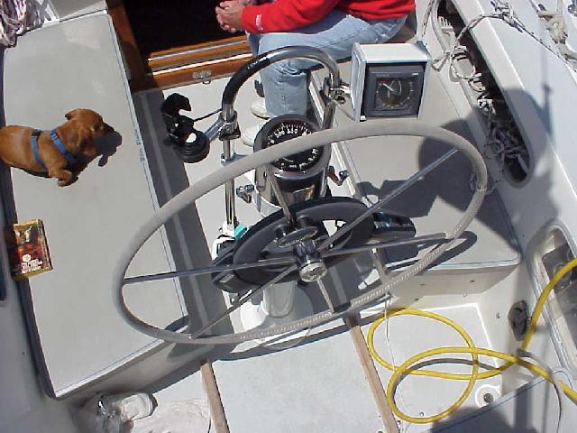
The best location for the autopilot control head will depend on whether you have a tiller or a wheel. In either case you should have an unobstructed view of the control head which is not blocked by passengers and crew and it should be within easy reach of a steering position without having to reach through the spokes of the wheel.
If you have a tiller a good location would be either high up on the back of the cabin or on the cockpit coaming in a location which is not a backrest. If you have a wheel you can mount it either to the port or starboard side of the cockpit coaming or better yet on a pod attached to the pedestal or the pipe handrail in front of the pedestal. You can phone Edison, the pedestal steering manufacturer, and request a catelog to order the parts directly from them. If mounted on the coaming I would prefer the starboard side since I am right-handed and the wiring would be easier to conceal in the lazerette than the quarterberth.
On my I36 I installed the Autohelm (now Ratheon) ST 4000 control head on top of an Edison single-lever throttle/shifter pod that I had installed when I repowered to a Yanmar diesel. This pod attaches with a plate to the starboard side of the pedestal and to a pipe that bolts to the cockpit floor where the fluxgate, power, throttle and shifter cables pass through. Edison has an optional accessory housing that mounts on top of this pod which they recommend can be used for installing a bow thruster control unit but the ST4000 control head fits perfectly over this housing which slopes aft for better visibility and egronomic access to the control head's buttoms.
I drilled a hole though the side of the pod immediately under the mounting plate for the wire for the wheel steering motor which is only a few inches away. I also drilled a second hole at this location for a GSP power/data cable. This power/data cable, which is an accessory from Garmin, plugs into the back of my Garmin 12XL. This hand held GPS attaches to the top of the pipe handrail in front of the pedestal with an optional bicycle handbar mounting bracket that is also available from Garmin for the 12XL.
This allows the boat to be steered by the GPS which is infinitely more accurate and reliable than steering by a compass heading selected on the autopilot's control head since your course is adjusted for leeway and you can go directly to the lat/lon of waypoint you selected or a series of waypoints on a route that you can create for longer passages. Garmin responded within a day to my e-mail inquiry on how to connect the GPS power/data cable to the Autohelm ST4000, after 4 years I stll am waiting for a reply from Raytheon.
Advantages of this setup is that the GPS can be quickly removed when the boat is docked and the GPS and Autopilot's buttons and LCD displays are egronomically accessible and visible from the central steering position.
If your ST4000 happens to have a anti-theft code number feature, I would strongly recommend that you send it back to Raytheon to permanently have this featured disabled. After a year my autopilot became inoperable when this antitheft feature activated itself for no apparent reason and I had to send the unit back to Raytheon to have it unlocked. I was lucky I still had my original purcahse reciept else Raytheon would not have fixed it. Raytheon noted when they returned the unit that they had permanently disabled the anti-theft feature and I have had no further problems.
I was lazy and anxious to try out the autopilot so I temporarily mounted my fluxgate compass high up, and as close to the center of the boat as possible on the lazerette side of the bulkhead next to the galley with the belief that this location may be too close to the magnetic influences of the engine. After calibrating the autopilot in my harbor's turning basin I ended up with a maximum of 2 degrees deviation which is well within the autopilot capability of correcting automatically for so I have never bothered to relocate it. Wherever you mount the fluxgate compass I would strongly recommend not cutting off the excess cable, but coiling the excess and securing it to a bulkhead for possible relocation in the future. If my initial lazerette location didn't work out (more than 5 degrees deviation) I was planning to relocate the fluxgate compass to the quarterberth side of the cabinet under the chart table as close as possible to the centerline of the boat. I definitely don't like the idea of puting a sensitive electronic instrument such as a fluxgate compass in the bilge!
Richard Balcom balcomr@cdsintl.com
Moku Uhane, Honolulu
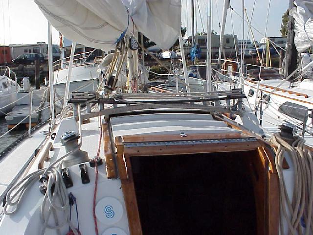
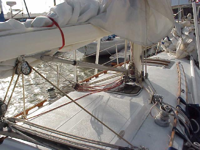
There are many boom vang arrangements on the I-36. The first picture is the very simple, old fashioned block and tackle style on Vanishing Animal. It's 4:1 purchase gives modest power, it acts as both a vang and a preventer, and can be positioned almost directly under the boom on all points of sail. It's disadvantage is that it has to be disconnected before each tack and reconnected afterwards.
There are many variations on the "standard" vang arrangement which involves a combination of a vang and twin preventers with control lines leading back to the cockpit. The first pic shows how Raspberry Tart uses a spring loaded vang and tacks the preventers at the base of the lower shrouds. Her control lines lead through fairleads on the side of the cabin and in through the aft end of the dodger.
The next two pics show how Natural High uses a 4 part tackle for a vang, then led her 4 part preventers out to the rail with the controls running outside the stantions along the rail and then inboard to cam cleats farther aft on the cockpit combing.
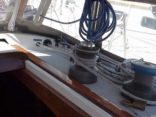
Silver Shadow goes for the 4 part vang, then uses a boom brake as a preventer. Her vang control is led back inside the dodger. Note the clean layout of control lines on the cabin top. (You can see them all under the Control Lines heading.)
From Jim Joubert
Mon Ami
September 1999
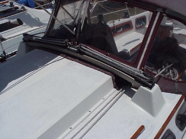
One area that could be touched upon under boom vangs is the main
justification for the rigid vang. i.e. to eliminate the topping lift.
When
I got my new full batten main, I found that the roach was so full at the
top that the topping lift would hang up on the number one batten on each
tack (bummer)! The solution was the rigid vang pictured. It holds the boom
up in lieu of the topping lift (which is now history), and holds the boom
down when running/reaching.
Still need the old 4 part vang as a preventer
though.
You won't hurt my feelings if you elect to leave the above out of your
already excellent coverage of vangs. Just thought I'd throw it in for what
it might be worth.
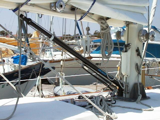 Mon Ami's new vang
I36 Mon Ami
Jim Joubert
Mail Jim
Click Pics to enlarge.
Go To Top
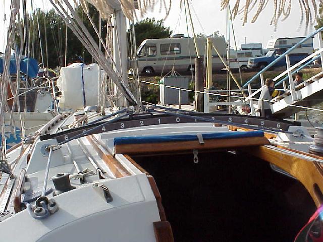
Travelers have evolved on these boats too. Once again, the 1973 version is shown on Vanishing Animal. It is a simple 3 part tackle running through cheek blocks on the sides of the deck mounts. The control lines run aft to the cockpit combing to cam cleats. Three part tackle, plus the curved design can be a challenge in the Bay's regular 20+ knot breezes. The track and car are Harken's medium size, installed easily in 1996 on the original curved channel base.
Blockbuster, just sold to Bill Higdon by Past Commodore and race winner Bruce Block, has "leveled the playing field" and even indroduced a slight upward curve so the tension on the main is the same at all points along the traveler. The 4 part control lines give better purchase and also lead aft to the cockpit. Note that neither of these ex-dedicated racers have the windage of a dodger. (Much to the annoyance of the First Mate!)
Also note the mainsheet in the first picture. The second picture shows the forward part of her 6 part mainsheet - one part more than the typical 5 part rig.
Raspberry Tart has the curved traveler base, but refitted with the larger Harken track and a 4 part purchase with less friction.
Compare these with the flat, narrow traveler on the 1982 built Natural High with its 3 part purchase. This traveler is only slightly wider than the main hatch, and means the vang and preventer need to do more of the work sooner as the main is eased.
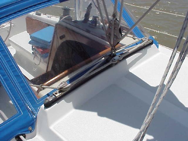
Here's another place to tuck those pesky control lines. Here Silver Shadow maximizes the use of leads, sheet stoppers, winches and cam cleats.
E-Mail Nancy & Al Farnum: sailsilvershadow@boatmail.com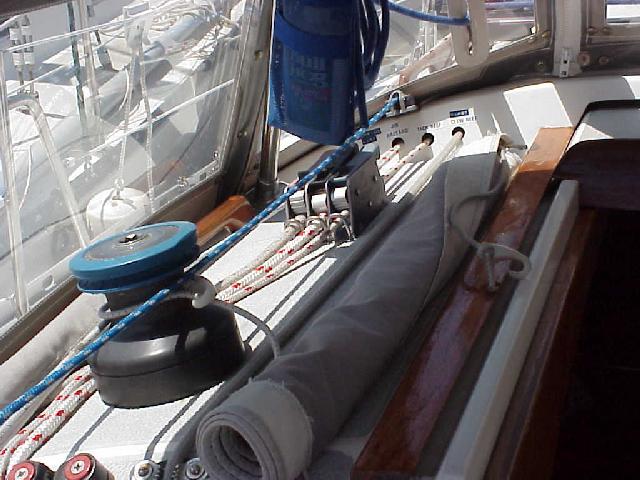
You thought someone was really going to tell their secrets??!! Send those secrets in!
Ok, Here's one very simple one to prime the pump. Note the numbers on Vanishing Animal's traveler. They are very handy for communicating to the crew how far to move the traveler, and then to duplicate the position on the oposite tack. Playing the traveler and vang are the easiest ways to cope with the Bay's strong breezes. For example, just moving the traveler 2 numbers to leeward can reduce heel and weather helm while increasing speed a tenth or two. Keep the main flat with the vang, but ease it down on the traveler until there is a slight backwind from the jib along the mast. You'll really notice a difference in the ease of steering, better speed, and much happier novices. There is nothing more discouraging to see than a boat with its rail in the water, rounding up in the puffs, and guests wondering if it will ever come back up.
From: ahamberg@mail.ivillage.com
Sent: Monday, July 15, 2002 9:11 AM
Subject: Question about short wisker pole on I36
Hi Gary,
Wondering if you can help me figure out how to rig the short wisker pole that came with my I36? One end has a fitting that I am not familiar with and no one at my marina seems to know how it works either.
On one end there is a pulley or sheve and a flat protrusion that extends past the pulley. It also has two eyes, one above and one below the pulley, presumably for guys? It's too short to go to the mast so I figure the inboard (Mystery) end goes to the rail (?) and is somehow is rigged with a line? It looks like you could run a line through the sheve and back to a winch ?
It seems that its secured to the sail in the normal fashion and the mystery end is the inboard end ?
There is a rough .jpg illustration of the unknown end attached. It's not to scale but accurately reflects the design.
 Click for larger image.
I do a lot of downwind sailing on Long Island Sound and would love to use it.
Thanks,
Anthony
From: John Melton
Sent: Wednesday, May 01, 2002 10:57 AM
Subject: Request for Roller Reefing Info
I'm a new member as of this year, but I haven't been able to participate in any of the club functions as yet. I just bought my Islander 36 in September of 2001. I'm in the process of looking into adding roller reefing to my 1977 Islander 36 "Freedom Won". I would like some recommendations for people/organizations that have done good work for other members in the past. I would like a general idea of things and pit falls to watch out for and of course price considerations. Any help that I receive will be greatly appreciated.
john.melton@ varian.com
Varian Medical Systems
Phone: 650-424-6080
John,
I had a Harken 1.5 unit installed on my I-36 at the end of 1999, so I've had about 18 months of experience with it. It was installed by South Beach Riggers 415-974-6063, for $2800. (Some people have put on the next larger size, a 2.0.)
There is an additional cost for converting your existing sails with hanks to a luff tape. This was about $400 per sail - done by North Sails. You may find a sailmaker who could do it for a little less, or less per sail if you do a couple at once.
One of the considerations when laying out your line is which side to come down, and how to lead the line. I happen to have mine on the starboard side (which is less common) because my spinnaker pole is already on that side and my shore power is run there too, so I've kept all of the "clutter" on one side. A common practice is to attach lead rollers or blocks to the lifeline stations. I chose to lead my line outside the stantions aft of the mast to keep the line out of the walking area on the deck. I did this by having the installers bolt small lead blocks to the toerail. I think there are just three, but they keep the line completely out of the way. The line terminates in a ratchet block with a cam cleat which is attached to the bottom of the stern pulpit stantion. It was recommended by the installers and has worked without a hitch. This arrangement has worked very well and it is right at the helm station so I can single handedly set and furl the jib from the helm.
It's worked without fail so far. It unrolls and rolls up relatively easily under most conditions. It is important to keep some tension on the jib sheet as you furl to get the sail tight around the headstay. I do this one of two ways: hold the furling line in my right hand and the sheet in the left and just move from starboard to port; or leave one turn of line around the winch. The first way works very nicely in lighter conditions, the second in heavier air where you need both hands on the furling line. In the heaviest of winds (say around 23+) I have put the pulling line on a winch to get it started due to the weight of wind in the sail while headed on roughly a close hauled course. The most strength is required when you start to furl since that is when there is the most sailcloth exposed. It gets easier as you roll it in.
I hose off the drum when I wash down at the end of a sail.
Being a racing man for most of my life, I was slow to go to roller furling, but my wife is it's biggest fan since I don't have to run forward to raise and lower the jib in the wild conditions on the Bay. I can (and often have) set and furled the jib while she's below.
Give me a call if you have any further questions.
Good luck,
Rick Van Mell vanmells@ix.netcom.com
Vanishing Animal
650-962-1515
Placeholder for your future ideas. (Send yours along to add to the list)
Under Construction
Go To Top
| Home Page Menu |