|
|
I-36 Maintenance & Improvements |
| This page is your gateway to lots of information about the care and maintenance of major components of the Islander 36, and includes enhancements, gadgets and other useful ideas. It's structure is to list major systems or areas of the boat, with sub-menus appearing with each selection - just move your cursor over an area of interest to see the sub-topics available, then slide over and click the one you want. Restructured in September 2005, this page combines the previous pages on Maintenance, Gadgets and Nav Systems all into one convenient page. We will continue to add information as a reference guide, so please send your contributions to: Webmaster@islander36.org |
In 1997, my surveyor pointed out a hairline crack in the gel coat at the bow running most of the way down. IHe thought these boats were built in two halves and then put together. He recommends grinding down and reglassing - but that makes it almost impossible to exactly match the gel coat. If I paint the hull one of these years I may do that. Another alternative (which I have not discussed with surveyor or yard) would be to do the reinforcing on the inside of the hull down to the waterline or as far as you can reach in the chain locker, then continue on down on the outside below the water line where you could easily cover the reinforced area with bottom paint.
From Matt Mikkelborg, 10/25/98 04:10:03 AM GMT
I just spent the day helping a friend on his 36 hauled out for a bottom job. I have an older Islander 32, also built in a two piece mold. I have the same cracking on the centerline described on your web page. The author of the letter should not be too concerned, as his cracks are not structural. Nor is his boat built in two pieces as implied in the note. The mold is in two halves by necessity to enable the removal of the finished hull. The mold is prepared, cleaned, waxed and gel coated with the two halves separated to ease the process. The mold is then mated and bolted together before the laminations begin, resulting in the solid, one piece, strong, thing of beauty Alan Gurney envisioned.
The cracking is in the flashing or extruded bit of gelcoat paste smeared on the flanges of the mold halves at joining. It is put there to ensure against any voids on the centerline of the finished part.(no mold has a perfectly fitted joint) Upon removal of the finished hull from the split mold this flashing is trimmed with a file or abrasive and polished to match the hull. The gelcoat paste is thicker than the thin uniform coating on the surrounding parts, and has little structural strength. It doesn't age as gracefully as the thinner gelcoat around it and eventually cracks and sometimes falls out in chunks. It is mainly a cosmetic problem, although it can provide an avenue for water penetration to the laminate. Some builders go to the trouble of gelcoating the flashing seam after removal from the mold. This will be evident down the road when a swath of gelcoat on the centerline will age differently and show this non molded application.
Matt Mikkelborg, mjmikkel@telebyte.com
 (Click to enlarge.)
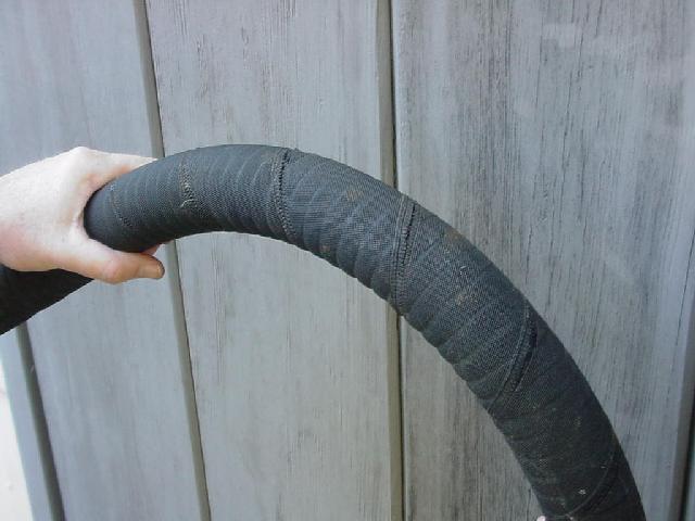
Great. Now I not only had a failed pump, but 28 feet of inch and a half hose
that had to be replaced and routed through some blind voids and around some
tight turns, something that a hose of that diameter just doesn't want to do.
But replace it, I did, 20 feet on the suction side and 8 feet on exhaust
side.
(Click to enlarge.)
Great. Now I not only had a failed pump, but 28 feet of inch and a half hose
that had to be replaced and routed through some blind voids and around some
tight turns, something that a hose of that diameter just doesn't want to do.
But replace it, I did, 20 feet on the suction side and 8 feet on exhaust
side. From: JimJoubert@cs.com
Sent: Monday, December 02, 2002 10:28 PM
Subject: Gadgets & Stuff
Mon Ami had rust stains emanating from the shroud/chainplates over to the toe rail. After a lot of cleaning, they would disappear only to show up again in a couple of weeks.
I decided the stains were caused by the morning dew condensing on the shrouds and then running down the shrouds to the deck. These small water droplets were carrying dirt and rust particles across the deck causing the stains.
To solve the problem, I installed small 3X5" kitchen sponges cut in half. Each half was attached to the shroud with plastic cable ties. The sponges soak up the moisture and retain it long enough to dry out during the day. No more stains!
When I hose off the boat it's amazing how much dirt flushes out of those sponges!
The sponges may not be very aesthetic, but they eliminate a lot of extra work. The small sponges with the 3M abrasive pads on one side are less conspicuous. You can cover them with shroud boots as I do, and they are out of sight.
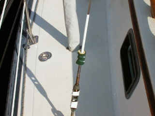 The Rust Stopper. (Click to enlarge.)
Jim Joubert
Window Curtains
2/21/02 From Gary SalvoHorseshoe Buoy
3/3/02 From Gary Salvo
Hi Rick,
Since we have owned I36 Holole�a over the past 5 years, the instruments have started failing, and in the case of the Standard Horizon wind instrument, died totally. The knotmeter, an analog model which in some ways is nicer to read than a digital meter, actually seized up in the meter movement itself. The depthsounder was replaced just after we got the boat with a Standard Horizon model and that actually was still working. It may get saved for a backup system mounted at the nav station. Doing a little snooping both at your September 2009 rendezvous, and when we got back home to Vancouver Island, yielded similar results. It seems that West Marine has the best prices on certain items such as electronics, both down your way in San Francisco, and here also. The choice was the Raymarine ST60 Plus system, speed, depth, and wind. The Raymarine system was one of the more reasonably priced of the various brands, the readouts for speed and depth are huge, all the bits and pieces are included, and it is a well known name.
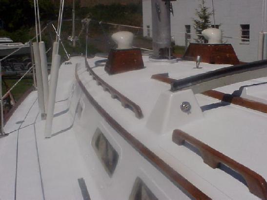
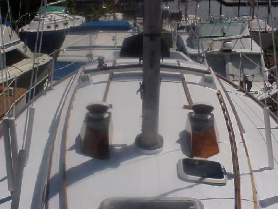
When Holole�a was hauled for bottom paint in October, the new depth and speed units were installed. Later, I got to go up the mast and fit the new masthead unit and fish the wires in, using the original wire for pulling the new one. As far as mounting the instruments, we wanted to get away from the usual reclining perches at the front of the cockpit seats, and we prefer instruments that everyone can see. It appears that companionway style pods have fallen out of favor for the binnacle mounted units, and are not readily available anymore. In our experience, the only person that can see the binnacle units is the helmsman and only if they are standing right behind the wheel. So a little woodworking solved that problem with a unique looking companionway pod.
Here are the photos of the new units installed in a pod that I made from a nice piece of 3/8 mahogany marine plywood I had stashed away. It was actually a section of floorboard from a long dead inflatable! The bracket was made from a few short lengths of 1� SS tubing and some fittings. A small wedge had to be used on the base fittings on each side of the companionway due to the slope of the cabin top. The base fittings are bolted on with �� flathead bolts, with fender washers and nylock nuts underneath. The wires are fed down the tubes and everything was well bedded. The interior liner had enough zippers that everything installed fairly neatly and easily inside. The wood pod was all epoxied together (no screws except for the removable face) and given one coat of epoxy before a coat of marine varnish. It should be reasonable watertight, and as it will live under a dodger it should all be fine.
Good sailing to all,
John and Marion Rodall, jmrodall@shaw.ca
11/6/09
![[Click to enlarge]](boatpics/hololea/hololea-001.jpg) Instruments 1 |
![[Click to enlarge]](boatpics/hololea/hololea-002.jpg) Instruments 2 |
![[Click to enlarge]](boatpics/hololea/hololea-003.jpg) Instruments 3 |
![[Click to enlarge]](boatpics/hololea/hololea-004.jpg) Instruments 4 |
![[Click to enlarge]](boatpics/hololea/hololea-005.jpg) Instruments 5 |
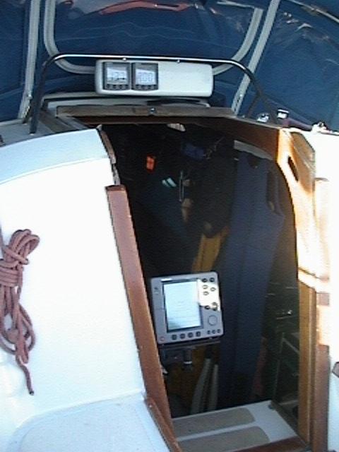 The new pod.
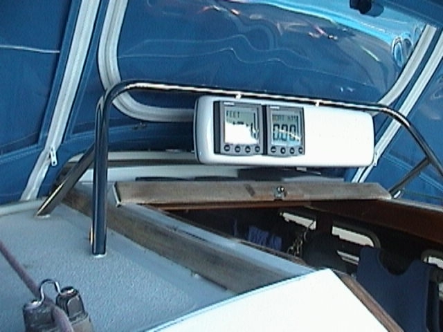 The instruments up close.
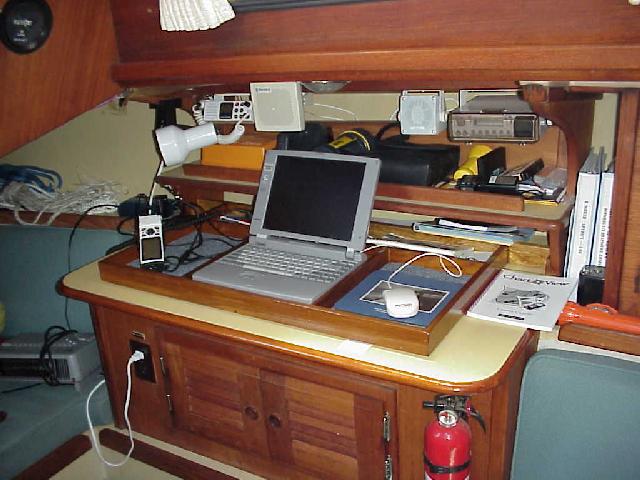
Don Henderson on Kindred Spirits fixed up this handy rig to hold a Garmin 45 GPS, and computer and paperwork. He is using Chart View. The GPS will pick up signals down below, though more slowly than when on deck. Its cord is long enough that it can be set on a cockpit seat to get faster response. Note the little blocks that hold the tray in place just above the "V" on the Chart View handbook.)
Above the nav station you can see their VHF and extra speaker which is on a long lead and can be easily moved to the cockpit. And finally, the stereo for tunes with one speaker whose pair is mounted forward on the head bulkhead.
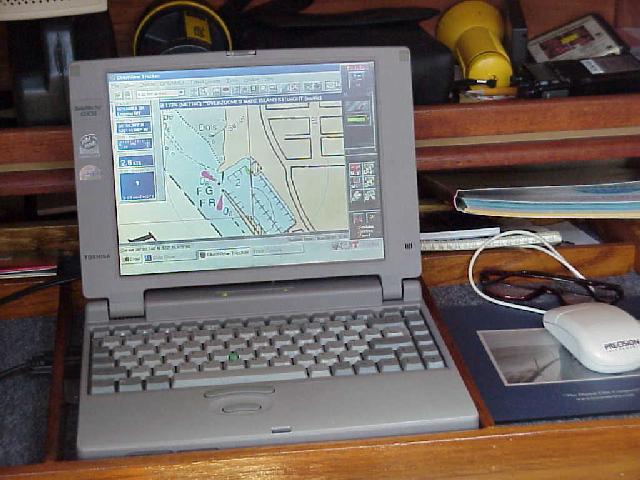
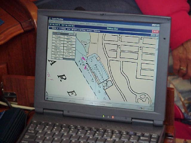
The second picture shows the level of detail available for Vallejo YC harbor, and you can just make out the small green boat shape located on the north end of the dock at the clubhouse - just where she was tied up for the picture.
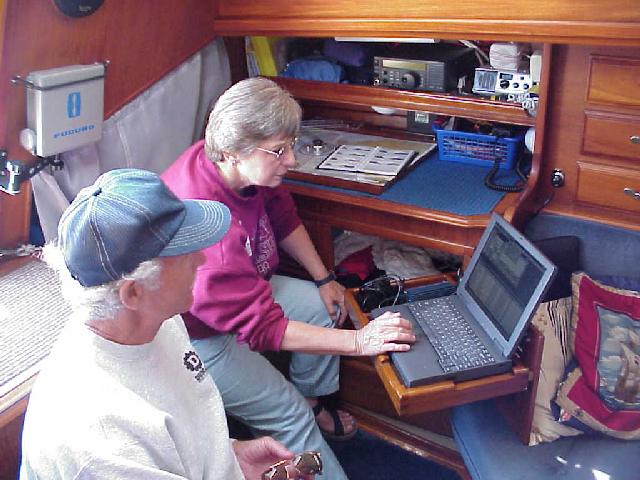
Nancy & Al Farnum are shoving off on Silver Shadow in July 1999 for a two month cruise down the coast of California to San Diego and back. They have done wondrous things to their boat for navigation and life at sea. The first picture shows Nancy at their computer table which swings out from the navigation locker. The table clicks in to a clip on the inside of the nav locker door for support. This angle is designed so the unit can be read from the cockpit bench. The computer is wired to the GPS which is mounted at the helm. The wiring includes both power and the computer connection so there is only one connection to be made when the GPS is installed. They use Cap'n software.
The computer table also has a support which drops down from the bottom and can be firmly connected to the frame of the nav locker to provide a very sturdy desk-like surface for extended work. A fold down seat has been built on the port side of the companionway steps to complete the installation. (Nancy is sitting on it!) Above the nav table there is the ham/SSB radio, and the VHF.
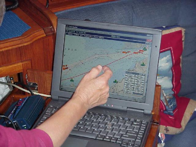
The second pic shows their view of Vallejo harbor, but the GPS is not turned on. The third pic shows how the system tracked their course up San Pablo Bay between Pt. Pinole and the entrance to the Napa River. The software even inserted the little red current direction and strength arrows.
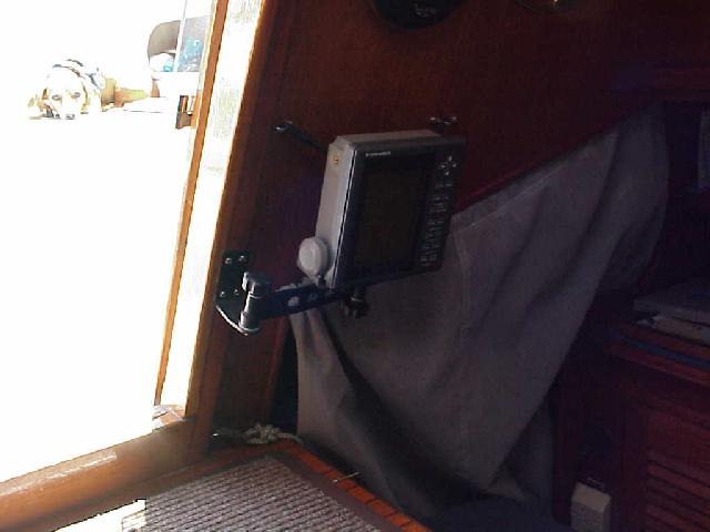
Oh yes, the radar unit is neatly mounted on a swing bracket so it can be read in the nav station or in the cockpit, as shown in pic four. The radar unit is neatly mounted on a stainless tube which runs about 10 feet up the permanent backstay. The backstay has integral insulators so most of it is the antenna for the SSB. This boat is ready for sea! (Sorry, a picture of the radar unit will have to wait for another day.)

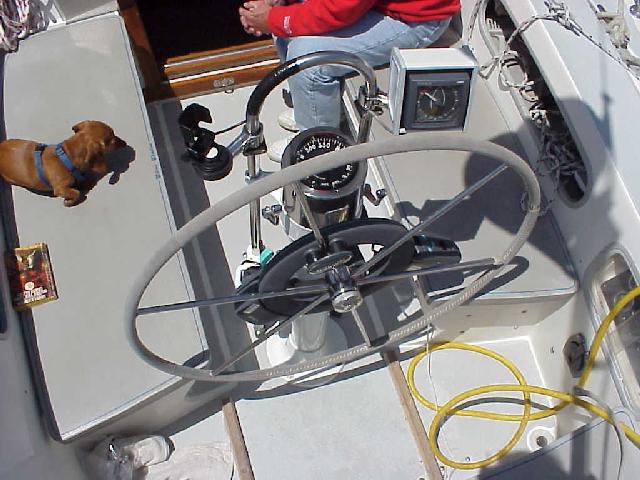
Al & Nancy Farnum's Silver Shadow has a terrific helm station - one of the most complete we've seen. The mount for the GPS is top left. The Navionics autopilot is totally self contained and clamps to the pedestal. Its power and remote control cable drops down the right tube, with the remote control on a telephone cord just inside the cabin. A relatively unique feature is that the auto pilot is tied to the apparent wind instrument and will act as wind-directed self-steering to maintain a constant angle to the wind. Great for trade wind sailing.
Wind info is the unit on the top left side. You can also just make out the cradle lower down on the left side for the hand-held VHF. Finally, note the foot braces on the cockpit floor.
This is so well rigged even Schatzie could probably steer it!
The best location for the autopilot control head will depend on whether you have a tiller or a wheel. In either case you should have an unobstructed view of the control head which is not blocked by passengers and crew and it should be within easy reach of a steering position without having to reach through the spokes of the wheel.
If you have a tiller a good location would be either high up on the back of the cabin or on the cockpit coaming in a location which is not a backrest. If you have a wheel you can mount it either to the port or starboard side of the cockpit coaming or better yet on a pod attached to the pedestal or the pipe handrail in front of the pedestal. You can phone Edison, the pedestal steering manufacturer, and request a catelog to order the parts directly from them. If mounted on the coaming I would prefer the starboard side since I am right-handed and the wiring would be easier to conceal in the lazerette than the quarterberth.
On my I36 I installed the Autohelm (now Ratheon) ST 4000 control head on top of an Edison single-lever throttle/shifter pod that I had installed when I repowered to a Yanmar diesel. This pod attaches with a plate to the starboard side of the pedestal and to a pipe that bolts to the cockpit floor where the fluxgate, power, throttle and shifter cables pass through. Edison has an optional accessory housing that mounts on top of this pod which they recommend can be used for installing a bow thruster control unit but the ST4000 control head fits perfectly over this housing which slopes aft for better visibility and egronomic access to the control head's buttoms.
I drilled a hole though the side of the pod immediately under the mounting plate for the wire for the wheel steering motor which is only a few inches away. I also drilled a second hole at this location for a GSP power/data cable. This power/data cable, which is an accessory from Garmin, plugs into the back of my Garmin 12XL. This hand held GPS attaches to the top of the pipe handrail in front of the pedestal with an optional bicycle handbar mounting bracket that is also available from Garmin for the 12XL.
This allows the boat to be steered by the GPS which is infinitely more accurate and reliable than steering by a compass heading selected on the autopilot's control head since your course is adjusted for leeway and you can go directly to the lat/lon of waypoint you selected or a series of waypoints on a route that you can create for longer passages. Garmin responded within a day to my e-mail inquiry on how to connect the GPS power/data cable to the Autohelm ST4000, after 4 years I stll am waiting for a reply from Raytheon.
Advantages of this setup is that the GPS can be quickly removed when the boat is docked and the GPS and Autopilot's buttons and LCD displays are egronomically accessible and visible from the central steering position.
If your ST4000 happens to have a anti-theft code number feature, I would strongly recommend that you send it back to Raytheon to permanently have this featured disabled. After a year my autopilot became inoperable when this antitheft feature activated itself for no apparent reason and I had to send the unit back to Raytheon to have it unlocked. I was lucky I still had my original purcahse reciept else Raytheon would not have fixed it. Raytheon noted when they returned the unit that they had permanently disabled the anti-theft feature and I have had no further problems.
I was lazy and anxious to try out the autopilot so I temporarily mounted my fluxgate compass high up, and as close to the center of the boat as possible on the lazerette side of the bulkhead next to the galley with the belief that this location may be too close to the magnetic influences of the engine. After calibrating the autopilot in my harbor's turning basin I ended up with a maximum of 2 degrees deviation which is well within the autopilot capability of correcting automatically for so I have never bothered to relocate it. Wherever you mount the fluxgate compass I would strongly recommend not cutting off the excess cable, but coiling the excess and securing it to a bulkhead for possible relocation in the future. If my initial lazerette location didn't work out (more than 5 degrees deviation) I was planning to relocate the fluxgate compass to the quarterberth side of the cabinet under the chart table as close as possible to the centerline of the boat. I definitely don't like the idea of puting a sensitive electronic instrument such as a fluxgate compass in the bilge!
Richard Balcom balcomr@cdsintl.com
Moku Uhane, Honolulu
| Home Page Menu |